
DA500-C
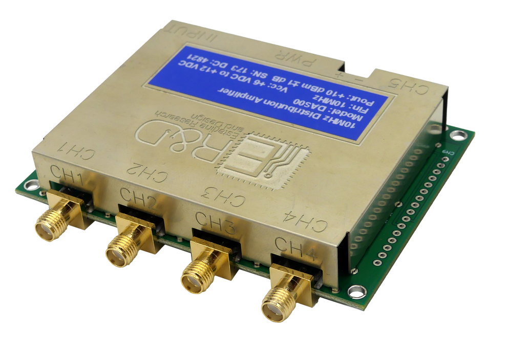
This page features the DA500-C model from our DA500 series of distribution amplifiers, equipped with SMA connectors on both front and back.
For alternative configurations within this series, please refer to the data sheet provided below.
Data Sheet:
![]() DA500 Series Specification Sheet
DA500 Series Specification Sheet
Mounting Fixture includes:
- 1x MHMF101 mounting bracket
- 4 x 4-40 F-F 3/16" hex spacers of length specified in drop-down box above
- 8 x 1/4" 4-40 black Oxide Phillips-head pan screws
- 4 x M3 x 12 pan head screws
- 4 x #8 1-1/2" long brass wood screws
Functional Description:
The primary function of our DA500 distribution amplifier is to distribute an existing signal to multiple points while preserving its integrity. The DA500 is ideal for situations requiring a low noise RF signal to be supplied to multiple usage points.
The DA500 has one input channel and five output channels. It may be configured with either SMA or BNC connectors (details provided in the connector table on page 4). The amplifier can be manufactured to support either 50Ω or 75Ω environments. This design provides multiple outputs of a modulated RF signal without the typical attenuation often associated with splitting of these types of signals. At most input frequencies, this results in amplification of the input, with the exception of the 450-500Mhz range. At these highest frequencies, the attenuation is no worse than -2dB, as seen in Fig. 4.
The single input is amplified to compensate for the fanout to the five output stages. Each output stage has isolation transformers for impedance matching and channel-to-channel isolation. This configuration achieves high fidelity transmission of the input signal up to five usage points.
For larger systems requiring more outputs, multiple amplifiers may be daisy-chained together by connecting the output of channel five to the input of another distribution amplifier.
Standard Specifications:

NOTES:
-
The device may be powered with a user-supplied voltage via the screw terminal connections or a 2.1 mm plug on a 6 V, 500 mA power module (a suitable module can be supplied upon request). When the power module is utilized, the module voltage is made available on the screw terminals, allowing the user to access 6 V, 250 mA to power external circuitry.
-
Max current specified is using a 500 MHz input.
Caution: Do not connect an external supply voltage to the screw terminals when using the power module.