
DA100-100M00-E

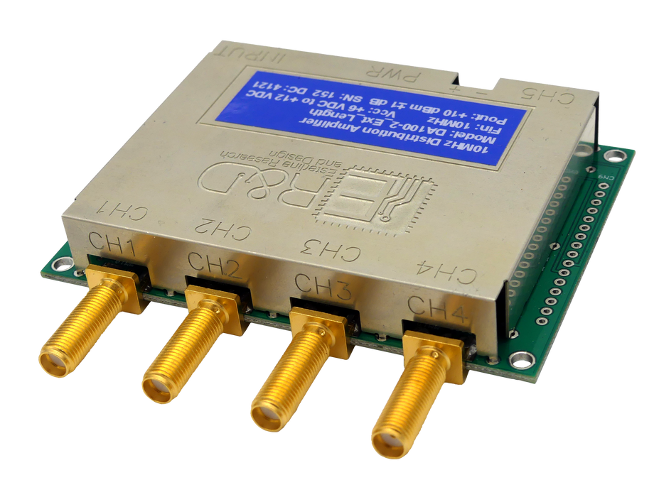
This page features the DA100-100M00-E model from our DA100 series of distribution amplifiers, designed for 100MHz operation and equipped with panel-mount SMA connectors on both sides.
For alternative configurations within this series, please refer to the data sheet provided below.


Mounting Fixture includes:
- 1x MHMF101 mounting bracket
- 4 x 4-40 F-F 3/16" hex spacers of length specified in drop-down box above
- 8 x 1/4" 4-40 black Oxide phillips-head pan screws
- 4 x M3 x 12 pan head screws
- 4 x #8 1-1/2" long brass wood screws
Functional Description:
The primary function of our DA100 distribution amplifier is to distribute an existing signal to multiple points while preserving its integrity. The DA100 is ideal for situations requiring a low noise RF signal to be supplied to multiple usage points.
The DA100 has one input channel and five output channels. It may be configured with either SMA or BNC connectors. The input is AC-coupled and has a 50 Ω source impedance. It includes a limiter circuit that not only provides a fixed output level but also offers high input gain. This design allows the amplifier to maintain the specified output power across a wide range of input power levels.
The input limiter is followed by three amplifier/low-pass filter stages, which insure low-distortion sine wave outputs. The outputs from the filter stages are supplied to fixed-gain output amplifiers. This configuration achieves channel to channel phase
offset of under 1 ns. The phase offset from the input to any output is less than 5 ns at 10 MHz.
For larger systems requiring more outputs, multiple amplifiers may be daisy-chained together by connecting the output of channel five to the input of another distribution amplifier. However, this configuration increases phase offset between amplifiers. If channel-to-channel phase offset is a concern, the recommended configuration would be to use a single amplifier to drive up to five additional amplifiers. This will provide up to 25 outputs with minimal channel-to-channel phase offset.
Standard Specifications:

NOTES:
- Input signal waveform can be any type with a 50% duty cycle.
- Amplifiers are purchased at a fixed frequency. Can accommodate any frequency between 1-100 MHz, with a minimum bandwidth of ± 5%.
- Min and max output characteristics specified is using a 10 MHz input.
- The device may be powered with a user-supplied voltage via the screw terminal connections or 2.1 mm plug on a 6 V, 500 mA power module (a suitable module can be supplied upon request). When the power module is utilized, the module voltage is made available on the screw terminals, allowing the user to access 6 V, 250 mA to power external circuitry.
- Max current specified is using a 10 MHz input.
- Caution: Do not connect an external supply voltage to the screw terminals when using the power module.